Weld Neck Vs Slip On Flanges Which Should You Choose

Get the flange wrong and you will not find out until the line is already under pressure.

Across oil and gas, water treatment, HVAC and general industrial piping, weld neck flanges and slip on flanges are the two designs engineers reach for most often. Both connect pipes, valves and equipment to the same ASME B16.5 dimensions, yet the way each one is built and welded changes how it handles stress, heat and vibration over the life of the system.

Choose poorly and the result is either a leak waiting to happen or money spent on strength a low pressure line never needed. Here is how the two compare and which one your project calls for.

What Is A Weld Neck Flange

A weld neck flange is built around a long tapered hub that narrows gradually from the flange body into the pipe wall. That taper does real work, spreading load evenly across the joint instead of letting stress pile up in one place.

The flange meets the pipe through a single full penetration butt weld, the same weld used to join one length of pipe to another. Because the bore lines up with the pipe bore, flow passes through with very little turbulence.

The design also pays off at inspection time, since that butt weld can be checked with radiographic or ultrasonic testing, giving engineers confidence in the joint before the line ever sees pressure.

These weld neck flanges are machined to standard pipe schedules in carbon steel, stainless steel and alloy grades, for exactly the high pressure and high temperature lines this design was built to handle.

What Is A Slip On Flange

A slip on flange takes a simpler approach. It is a flat ring with a bore just large enough for the pipe to slide through.

Once it is in position, two fillet welds hold it in place, one on the outer face and one on the inner bore. There is no tapered hub here, so the transition from pipe to flange happens more abruptly than it does on a weld neck design.

That simplicity is the point. Slip on flanges go on faster, align more easily and forgive a pipe that was cut slightly long or short, all while costing less to produce. The same material range is available as slip on flanges for cooling water, compressed air, HVAC and other utility lines where speed and cost outweigh the need for extreme pressure ratings.

Weld Neck Vs Slip On Flange Key Differences

The table below lines up both flange types against the factors that actually decide a specification.

Factor Weld Neck Flange Slip On Flange
Weld Type Single full penetration butt weld Two fillet welds
Stress Distribution Gradual through tapered hub More concentrated at weld toe
Bore Alignment Matches pipe bore exactly Slightly larger than pipe
Fatigue Resistance Higher Lower
Weld Inspection Radiographic or ultrasonic testing possible Surface testing only
Installation Speed Slower, needs precise alignment Faster, easier fit up
Material Cost Higher Lower
Best Suited For High pressure and critical service Low to moderate pressure service

When To Choose A Weld Neck Flange

Reach for a weld neck flange whenever a joint cannot fail.

  • High pressure systems rated Class 300 and above
  • High temperature lines that expand and contract often
  • Piping near pumps or compressors that creates vibration
  • Lines carrying hazardous, toxic or flammable fluids
  • Projects where the weld must pass radiographic testing
  • Systems where long term reliability matters more than upfront cost

When To Choose A Slip On Flange

A slip on flange earns its place wherever conditions stay steady and budget matters as much as build.

  • Low pressure utility lines such as cooling water or compressed air
  • HVAC and general building piping
  • Water treatment and distribution networks
  • Temporary, test or bypass connections
  • Large diameter, low pressure lines where material cost matters most
  • Sites where pipe length on the ground may vary slightly

Cost And Installation Comparison

A slip on flange almost always costs less than its weld neck equivalent, simply because it uses less material and a simpler welding method.

How much you actually save depends on size and pressure class, as the table below shows.

Pressure Class Typical Cost Gap Installed Cost Note
Class 150 Slip on runs around 20 to 30 percent cheaper Gap narrows once welding labour is added
Class 300 Slip on stays moderately cheaper Extra weld inspection can close the gap
Class 600 and above Weld neck is usually required Cost difference becomes far less relevant

Whatever the size, total installed cost should weigh in welding labour and inspection, not just the sticker price of the flange itself.

Where To Source Flanges In The UAE

Beyond weld neck and slip on types, K. Hashim LLC works as a complete flanges supplier in UAE.

The range covers blind, lap joint, plate, socket weld, spectacle and threaded flanges in carbon steel, stainless steel and alloy grades, so every flanged connection on a project can come from one source.

Conclusion

Both weld neck and slip on flanges earn their place once the operating conditions are clear.

Weld neck flanges suit high pressure, high temperature and cyclic service where strength and inspection matter most, while slip on flanges suit stable, low pressure utility lines where cost and installation speed take priority.

Weigh up pressure class, temperature, vibration and what a leak would cost you before you order, and the right choice becomes obvious.

Get Expert Help Choosing The Right Flange For Your Project

Getting the choice between weld neck and slip on flanges right protects the safety, performance and long term cost of a piping system.

K Hashim LLC supplies certified weld neck and slip on flanges across multiple sizes, classes and materials for oil and gas, construction and industrial projects throughout the UAE.

Reach out to our team for guidance on choosing the right flange for your system.

Explore More Expert Insights

Explore our expert insights to stay updated on the latest piping solutions, flange types, and industrial best practices.


Stud Bolts vs Hex Bolts: Which Fastener Is Right for Your Application?

When engineers and procurement specialists sit down to plan a project, fastener selection is one of the first real decisions on the table. Choosing between stud bolts and hex bolts carries direct consequences for joint integrity, sealing performance, and long-term maintenance costs. Both fasteners hold assemblies together but they do it in fundamentally different ways, and the wrong choice can result in leaks, loosening, and unplanned downtime that no project budget accounts for.

What makes this decision worth getting right is that these two fasteners are not interchangeable alternatives. They are purpose-built for different conditions, different loads, and different service environments.

Understanding what separates them at a mechanical level and knowing where each one performs at its best is what allows engineers, contractors, and procurement teams to make a specification they can stand behind.

What Are Stud Bolts?

Stud bolts are headless, fully or partially threaded rods that secure joints using nuts on both ends. Both ends thread into the assembly and the clamping force is distributed evenly across both nuts. This headless design makes them well suited for tight or confined spaces where a bolt head would obstruct access or create an uneven bearing surface.

Industries like oil and gas, petrochemicals, and power generation rely on stud bolts almost exclusively for flanged pipeline connections and pressure vessels where leakage cannot be tolerated.

Common types of stud bolts

  • Fully threaded studs with threads running the entire length for maximum grip
  • Double-end studs with threads at both ends and a plain shank in the middle
  • Tap-end studs with different thread lengths at each end for use with tapped holes

What Are Hex Bolts?

Hex bolts are one-piece fasteners with a six-sided head and a threaded shank, tightened using a wrench or socket applied directly to the head. This makes installation fast and practical in applications where access is limited to one side of the assembly. Their availability across multiple grades, sizes, and materials makes them the standard choice for construction frames, machinery housings, automotive assemblies, and equipment brackets.

Common types of hex bolts

  • Standard hex bolts with partial thread and plain shank for clearance hole applications
  • Fully threaded hex bolts with threads along the full shank for shorter grip applications
  • Flange hex bolts with an integrated flange under the head for wider load distribution

Key Differences Between Stud Bolts and Hex Bolts

The differences between these two fasteners go deeper than appearance. Understanding the mechanical behavior of each one helps engineers match the right fastener to the right service condition.

Feature Stud Bolts Hex Bolts
Head Design No head, nuts on both ends Hexagonal head, one nut
Torque Application Applied to nuts, not the stud body Applied directly to the bolt head
Load Distribution Even across both ends Concentrated at the head end
Access Requirement Both sides of the joint needed Single-sided access is sufficient
Typical Pressure Rating Up to PN40 and above Typically up to PN16
Best Environment High pressure, high temperature General structural and mechanical
Maintenance Nuts can be split without damaging the stud Head can round off or seize in tapped holes

Installation Method and Access Requirements

Hex bolts only need access from one side of the joint, which makes them convenient for blind-hole applications and tight assemblies where reaching behind the component is not possible. A single wrench or socket drives them in and secures the connection without any additional hardware on the reverse side.

Stud bolts require clear access to both sides of the joint because a nut must be fitted and tightened on each end. This is not a limitation in most flange applications since through-access is standard, but it does rule stud bolts out for blind-hole situations where one side is inaccessible.

Load Distribution and Clamping Force Accuracy

When torque is applied to the head of a hex bolt, a meaningful portion of that energy is absorbed by friction between the head bearing surface and the mating component and between the thread flanks. The bolt body also experiences torsional stress as it rotates and this twisting does not contribute to clamping force, making precise and repeatable preload harder to achieve.

Stud bolts handle this differently. Torque goes only to the nut, the stud body goes into pure tension, and the clamping force is far more accurate and uniform. For gasketed joints where even a small difference in compression across the sealing face can cause a leak, this distinction is critical to reliable performance.

Performance in High Pressure and High Temperature Service

For pipelines, pressure vessels, heat exchangers, and reactors, stud bolts are not just preferred — they are specified by code. Standards like ASME B16.5 mandate stud bolts for flanged connections in critical service because their pure-tension loading method ensures the gasket is compressed uniformly across the entire sealing face.

Even when the system goes through thermal cycling with expansion and contraction from temperature changes, a properly preloaded stud bolt maintains joint integrity in a way that a hex bolt typically cannot. Hex bolts perform reliably in moderate-stress structural applications but the stress concentration at the head-shank junction becomes a liability under sustained high loads or dynamic vibration.

Explore a complete range of industrial stud bolts and hex bolts in materials and grades suited for both standard and critical service conditions.

Material Options and Corrosion Resistance

Both fastener types are available in carbon steel, alloy steel, and stainless steel, but the material specifications most commonly associated with each reflect their typical service environments. Stud bolts in high-temperature piping are most often manufactured to ASTM A193 Grade B7, a chromium-molybdenum alloy that retains strength at temperatures up to around 482°C and is typically paired with ASTM A194 Grade 2H heavy hex nuts.

For higher temperatures approaching 593°C, Grade B16 is used. Hex bolts in structural applications commonly follow ASTM A325 or A307 grades, while stainless steel grades are available across both types for environments involving moisture, chemicals, or marine exposure.

Maintenance, Replacement, and Long-Term Cost

If a hex bolt seizes in a tapped hole due to corrosion or over-torquing, the head can round off and extracting it often means drilling out the fastener and re-tapping the hole, which is a costly and time-consuming repair. The issue is compounded in critical systems where downtime carries financial and safety implications.

With stud bolts, the exposed nuts absorb wear and corrosion first. A seized or damaged nut can be split and removed without touching the stud itself, and the stud can often be reused or replaced without disturbing the flange or surrounding components. In systems that undergo regular inspection and maintenance cycles, this serviceability advantage adds up considerably over time.

Choosing the Right Fastener for Your Project

If the connection involves a gasketed flange, operates under elevated pressure or temperature, or sits inside a system where leakage would be dangerous or costly, stud bolts are the right choice. If the connection is structural, mechanical, or general-purpose and operating conditions are stable, hex bolts offer practical and cost-effective performance.

Budget plays a role as well. Hex bolts are widely available and easy to source in bulk at competitive prices, while stud bolts carry a higher unit cost that is easily justified by their service life and reliability in demanding environments. Getting the selection right at the specification stage avoids costly corrections later in the project lifecycle.

Conclusion

Stud bolts and hex bolts each have a clear role in industrial and structural applications. Stud bolts deliver the precise clamping force, sealing integrity, and maintenance flexibility that high-pressure and high-temperature systems demand. Hex bolts bring versatility, ease of installation, and broad availability to the full range of general-purpose fastening needs. Selecting the right one from the start protects the integrity of the connection and reduces the risk of failures down the line.

Hashim LLC supplies high quality bolts and fastening components designed to meet the demands of industrial operations across the UAE, from standard structural assemblies to critical high-pressure pipeline systems.

Partner with our fastener specialists for dependable bolt solutions tailored to your project specifications and operating requirements.

Explore More Expert Insights

Explore our expert insights to stay updated on the latest piping solutions, flange types, and industrial best practices.

Nylock nuts vs Standard Nuts: Key Differences Explained

In industrial and mechanical applications, loose fasteners can lead to equipment damage, maintenance issues, and safety risks. Choosing between a Nylock nut and a standard nut is important for maintaining secure threaded connections, especially in environments exposed to vibration and dynamic loads.

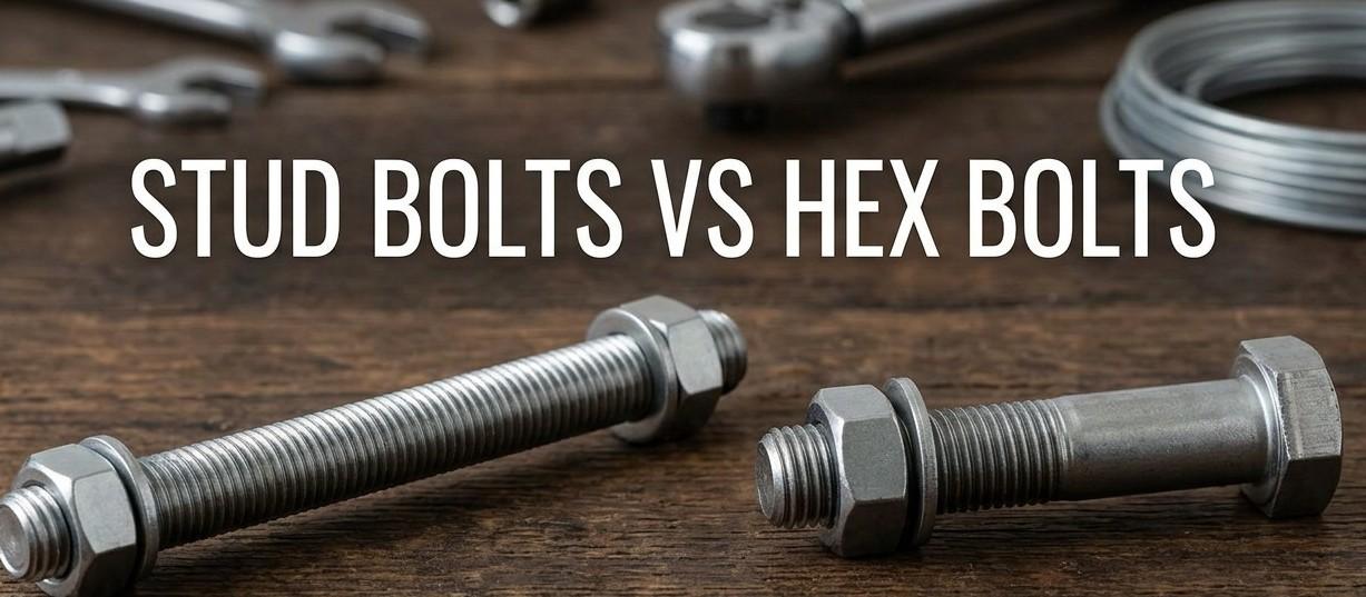
Although both fasteners serve the same basic purpose, their locking mechanisms work very differently. Standard nuts rely on thread friction and clamp force, while Nylock nuts use a nylon insert that creates prevailing torque to resist loosening during operation.

This guide explains the differences between Nylock nuts and standard nuts, including vibration resistance, temperature performance, reusability, and material options. It also helps identify which fastening solution is best suited for specific industrial and mechanical applications.

What Is a Standard Nut?

A standard nut, often called a hex nut, is the most widely used fastening component in mechanical assemblies worldwide. It threads onto a bolt and is torqued down to a specified value, generating a clamping force between the mating surfaces.

That clamping force creates friction between the threads, and friction is what holds the joint together. Standard nuts depend entirely on preload to stay in position since they carry no independent locking feature of their own.

In a perfectly static environment this friction keeps the nut in place for years. The moment an assembly starts to vibrate, however, the nut becomes vulnerable to gradual rotation and backing off.

Standard nuts conform to DIN 934 or ANSI B18.2.2 and come in a range of materials and grades. Key characteristics include:

  • Available in carbon steel, stainless steel, brass, and alloy steel
  • Free-spinning design allows fast hand installation before final torque
  • Unlimited reusability as long as threads remain undamaged
  • Lower unit cost compared to any locking nut variant
  • Require additional measures like lock washers in vibrating environments

What Is a Nylock nut?

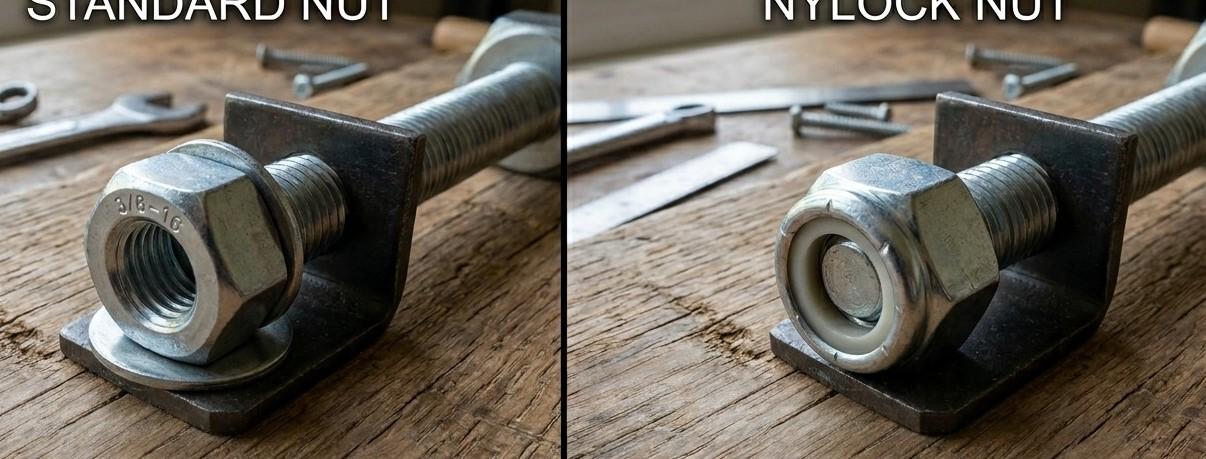
A Nylock nut, also called a nylon insert lock nut, features a nylon collar embedded in the top portion of the nut. When bolt threads reach this collar they must force their way through the nylon, which deforms slightly and grips the bolt with consistent compressive pressure.

This grip is what makes the Nylock nut fundamentally different. The locking action does not come from bolt tension or clamp force but from the mechanical interference between the nylon and the thread flanks.

This means the nut resists rotation even when vibration reduces or eliminates the original clamp load. The nylon insert is typically made from polyamide, which retains its elastic recovery properties across a wide temperature range for general industrial use.

Core features of a Nylock nut include:

  • Nylon collar permanently bonded inside the top of the nut body
  • Prevailing torque that holds the nut even after bolt tension is lost
  • Dimensional compliance to ISO 7042 or ISO 7043 depending on variant
  • Available in steel, stainless steel, and titanium base materials
  • Not free-spinning, requiring a wrench through the nylon engagement zone

How the Locking Mechanism Actually Works

When a standard nut is tightened, the friction holding it in place comes from two contact zones. The first is between the underside of the nut and the bearing surface, and the second is between the mating thread flanks of the nut and bolt.

Research using the Junker vibration test, the globally accepted standard for fastener loosening behavior, consistently shows that transverse vibration overcomes these friction zones far more easily than axial loading. Once friction drops below the self-loosening threshold, the nut begins to back off one microscopic increment at a time.

A Nylock nut adds a third retention mechanism that does not depend on thread friction at all. The nylon collar creates prevailing torque, which is resistance that exists independently of bolt tension.

Even if vibration strips away all clamp load, the nylon still grips the bolt and holds the nut in position. Laboratory testing confirms that Nylock nuts retain their position through thousands of vibration cycles where standard nuts have already fully backed off.

Key Differences Between Nylock nuts and Standard Nuts

The table below summarizes the most important performance and application differences between the two nut types to support clear procurement decisions.

Feature Standard Nut Nylock Nut
Locking Mechanism Thread friction only Nylon insert creates prevailing torque
Vibration Resistance Low High
Temperature Limit Limited by material only Nylon softens around 120–250°C
Reusability Unlimited Reduced after each removal
Installation Torque Standard torque at seating only Higher torque required through nylon zone
Typical Materials Carbon steel, stainless steel, brass Steel or titanium with nylon insert
Thread Damage Risk Minimal Low, nylon adds slight resistance
Cost Lower upfront Higher upfront, lower lifecycle cost
Best Environment Static, non-vibrating assemblies Dynamic loads, vibration, safety-critical joints
Applicable Standards DIN 934, ANSI B18.2.2 ISO 7042, ISO 7043, DIN 985

Material Options and Their Significance

Both nut types are available across multiple material grades, and the right choice depends on the environmental conditions the assembly will face. The three main tiers are carbon steel, stainless steel, and titanium.

Carbon steel

Carbon steel Nylock nuts and standard nuts are the most economical option for dry indoor environments where corrosion is not a concern. They are widely used in general machinery, consumer products, and construction applications.

Stainless steel

Stainless steel versions offer improved corrosion resistance and work well in food processing, mild marine environments, and chemical handling equipment. One trade-off is that stainless on stainless can gall without lubrication, so an anti-seize compound is recommended during installation.

Titanium

Titanium represents the highest performance tier for both nut types. Titanium alloy grade 5, known as Ti-6Al-4V, delivers a tensile strength of approximately 130,000 psi at a density roughly 40 percent lower than steel.

Its passive oxide layer regenerates after surface scratching, providing corrosion resistance that far exceeds stainless steel in saltwater and acid environments.

When a reputable Nylock nuts supplier combines titanium with a high-grade nylon insert and manufactures to ISO 7043, the result is a fastener suited for aerospace, offshore, and advanced medical applications.

Titanium Nylock nuts offer specific advantages that no other material combination can match:

  • Weight savings of up to 40 percent compared to equivalent steel fasteners
  • Self-healing oxide layer that resists saltwater, acids, and chloride attack
  • Fatigue strength retention up to 50 percent of ultimate tensile strength after one million stress cycles
  • Biocompatibility making them suitable for medical device and implant tooling
  • No coating required, eliminating coating wear and delamination over time

Temperature Performance and Its Limits

Temperature behavior is one of the most critical factors when selecting between these nut types, especially in industrial and mechanical environments operating near heat sources.

Standard nuts have no polymer component, so their temperature range is governed entirely by the alloy used. High-grade steel nuts can function in temperatures well above 500 degrees Celsius in non-oxidizing conditions without any loss of mechanical performance.

Nylock nuts carry a built-in temperature constraint because nylon loses its elastic recovery when heated beyond its softening point. Standard polyamide inserts begin to soften around 120 degrees Celsius and lose meaningful locking force above that threshold.

Higher-specification nylon grades extend the usable range to approximately 250 degrees Celsius. Applications involving these environments typically require an upgraded insert:

  • Exhaust systems and turbocharger mounting brackets
  • Heat exchanger flanges and industrial boiler connections
  • Engine compartment fasteners near hot surfaces
  • Industrial ovens and furnace equipment enclosures
  • Hydraulic systems operating at sustained elevated temperatures

Above 250 degrees Celsius, all-metal distorted-thread locking nuts are the appropriate choice. A reliable nylock nuts supplier will provide technical data sheets showing locking torque retention at each temperature level for every product in their line.

Vibration Resistance: The Defining Test

Vibration testing is where Nylock nuts prove their value most clearly and where the limitations of standard nuts become impossible to ignore.

The Junker test applies controlled transverse vibration to a bolted joint and measures the rate at which the nut backs off. Standard hex nuts begin to loosen within the first few hundred cycles and typically reach near-zero preload within a few thousand cycles depending on amplitude and frequency.

Nylock nuts tested under identical conditions retain their position across tens of thousands of cycles. Even after bolt elongation relaxes and tension drops, the nylon collar keeps the nut from rotating backward on the thread.

Industries that have adopted Nylock nuts specifically for vibration control include:

  • Automotive manufacturing for chassis, suspension, and drivetrain connections
  • Commercial aviation for engine mounts, landing gear, and control surface linkages
  • Rail equipment assembly for bogies and underframe structural joints
  • Industrial pump and motor construction operating under continuous cyclic loads
  • Marine vessels exposed to constant engine vibration and wave-induced movement

This performance advantage translates directly into reduced maintenance intervals, fewer fastener-related failures, and greater overall system reliability.

Reusability and Maintenance Considerations

One practical limitation of Nylock nuts is their reduced reusability compared to standard nuts. Each time a Nylock nut is removed from a bolt, the nylon insert undergoes some permanent deformation, so the prevailing torque on the second installation is lower than on the first.

Engineering standards and most fastener manufacturers recommend replacing Nylock nuts after disassembly, particularly in safety-critical applications. The reason is reliability rather than cost, since the price of a replacement nut is negligible compared to the risk of a failed joint.

Standard nuts can be reused indefinitely as long as threads are undamaged. This makes them the practical choice for components requiring frequent removal such as:

  • Inspection panels and maintenance access covers
  • Test fixtures and laboratory equipment
  • Adjustable frames and production jigs
  • Consumer products designed for user servicing
  • Any assembly where fastener removal happens on a regular schedule

When to Choose a Nylock nut?

Selecting the right nut type starts with an honest assessment of the operating environment. Nylock nuts are the correct specification in the following situations.

The assembly experiences vibration from any source. Engine harmonics, road input, equipment cycling, and fluid pulsation all create the transverse movement that gradually backs off standard nuts over thousands of operating hours.

The joint is safety-critical and a loose fastener could cause injury or equipment failure. Applications in this category include:

  • Steering linkages and tie rod ends
  • Brake caliper and master cylinder mounting
  • Overhead hoists and lifting equipment
  • Structural connections in bridges and elevated platforms
  • Aircraft control surface and landing gear assemblies

The assembly is difficult or expensive to access for routine retightening. Remote installations, buried components, and permanently enclosed assemblies benefit from the set-and-forget reliability that Nylock nuts provide between service intervals.

The joint material is soft or prone to creep such as aluminum, plastic, or composite structures. As the bearing material compresses and preload drops over time, the nylon insert keeps the fastener from backing out entirely.

When to Choose a Standard Nut?

Standard nuts remain the dominant fastener by volume for valid engineering reasons. Specifying Nylock nuts across every application adds unnecessary cost and complexity without improving performance.

Purely static structural assemblies such as building frameworks, shelving systems, and non-vibrating enclosures do not generate the transverse motion that causes loosening. Standard nuts with correct torque values are fully adequate in these conditions.

Standard nuts are also the better choice in the following scenarios:

  • High-precision torque applications like cylinder head bolts where consistent friction coefficients are essential for accurate torque-to-yield readings
  • Assemblies requiring frequent disassembly such as inspection panels and test fixtures where a new locking nut would be needed every time
  • Cost-sensitive, low-risk applications where the consequences of a loose nut are minor and do not justify the added expense
  • Applications using thread-locking compounds as the primary retention method where a nylon insert would interfere with compound adhesion
  • Precision bearing preload adjustments where controlled, repeatable friction is critical to correct function

Procurement and Supplier Selection

For industrial buyers, fastener quality depends as much on the manufacturing process as on the design specification. Dimensional compliance to ISO 7043 or DIN 985 ensures interchangeability, but nylon insert consistency, bonding method, and thread accuracy all directly affect real-world locking performance.

When evaluating a Nylock nuts supplier for critical applications, the baseline requirement is ISO 9001 certification covering the full manufacturing process. Aerospace supply chains require AS9100 certification and medical applications require ISO 13485.

Beyond certification, procurement teams should verify the following before placing orders:

  • Material test reports with chemical composition and mechanical property data for each batch
  • Lot traceability documentation linking finished fasteners back to raw material heat numbers
  • Sample locking torque test data confirming prevailing torque values meet or exceed ISO minimums
  • Production capacity and minimum order quantities that align with project volume requirements
  • Availability of stock in standard sizes to support urgent or unplanned maintenance requirements

Lead times for specialty sizes and materials, particularly titanium, typically range from eight to twelve weeks for custom orders. Building this into project schedules and confirming stock availability for common sizes will prevent delays during critical assembly phases.

Conclusion

The choice between Nylock nuts and standard nuts comes down to operating conditions, joint criticality, and long-term fastening reliability. Standard nuts provide a practical and cost-effective solution for static, low-vibration applications where regular maintenance and frequent disassembly are expected. Nylock nuts offer superior resistance against loosening in environments exposed to vibration, dynamic loads, and continuous movement, making them ideal for safety-critical and high-performance assemblies.

K Hashim LLC supplies premium titanium Nylock nuts and precision-engineered titanium fasteners designed to meet the demands of aerospace, marine, petrochemical, and industrial applications worldwide, from standard ISO 7043 configurations to custom manufacturing specifications.

Contact our fastener specialists for technical guidance, material certifications, and dependable fastening solutions tailored to your project requirements.

Explore More Expert Insights

Explore our expert insights to stay updated on the latest piping solutions, flange types, and industrial best practices.

Weld Neck vs. Slip-On Flanges: Which One Should You Choose?

Choosing the wrong flange type can lead to leaks, system failures, costly downtime, and serious safety risks. When comparing weld neck vs. slip-on flanges, the right choice depends on your operating pressure, temperature, installation requirements, and long-term reliability needs.

This guide breaks down the key differences, technical specifications, and ideal applications for both flange types helping you make the right decision for your piping system.

What Is a Weld Neck Flange?

A weld neck flange features a long tapered hub that gradually transitions into the pipe wall, distributing stress evenly across the joint. It connects to the pipe via a full-penetration butt weld, which can be radiographically or ultrasonically tested to verify weld integrity under ASME B16.5 and ASME B31.3 requirements.

The tapered hub is the defining feature: it transfers load progressively into the pipe wall, minimizing stress concentration at the joint. This makes weld neck flanges the preferred choice wherever structural integrity and inspect ability are non-negotiable.

Where Weld Neck Flanges Perform Best

  • High-pressure and high-temperature piping systems
  • Oil and gas pipelines and petrochemical operations
  • Refinery and offshore platform installations
  • Power generation steam systems
  • Cryogenic fluid handling
  • Any service where joint failure carries catastrophic consequences

What Is a Slip-On Flange?

A slip-on flange slides over the pipe end and is secured with two fillet welds — one on the hub face and one at the internal bore. The bore is machined slightly larger than the pipe outside diameter, allowing easy alignment and faster fit-up before welding.

Without the tapered hub found on weld neck flanges, slip-on flanges are simpler to install and more economical to procure. However, the fillet weld design offers less structural integrity, making them best suited to lower-pressure, lower-risk applications.

Where Slip-On Flanges Are the Practical Choice

  • Water distribution and utility piping
  • HVAC and cooling systems
  • General industrial and low-pressure service lines
  • Food and beverage processing
  • Maintenance, repair, and retrofit scenarios

Weld Neck vs. Slip-On Flanges: Key Technical Differences

1. Strength and Pressure Tolerance

The tapered hub of a weld neck flange transfers load gradually into the pipe wall, reducing stress concentration and supporting pressure ratings up to Class 2500 under ASME B16.5. Slip-on flanges rely on two fillet welds, which are inherently less robust. Their effective pressure capacity is typically around two-thirds that of an equivalent weld neck under the same class rating, making them suitable for low-to-medium pressure applications only.

2. Welding Method

Weld neck flanges use a full-penetration butt weld, which forms a seamless, high-integrity connection with the pipe. Slip-on flanges use two fillet welds — faster to deposit, but less structurally sound. The fillet weld creates a geometric discontinuity at the weld toes, which becomes a potential fatigue initiation point under cyclic or dynamic loading.

3. Radiographic Testing and Code Compliance

The butt weld on a weld neck flange can be radiographically tested (RT) or ultrasonically tested (UT) to confirm internal weld integrity, as required under ASME B31.3 and API 570 for critical service. Fillet welds on slip-on flanges cannot be RT examined. This typically excludes them from Category M fluid service, lethal service designations, and any application where full volumetric weld examination is mandatory.

4. Fatigue and Cyclic Load Performance

In systems subject to vibration, thermal cycling, or pressure surges, the butt-weld joint of a weld neck flange delivers superior fatigue resistance due to more uniform stress distribution. Slip-on fillet welds are more susceptible to fatigue cracking under repeated dynamic loading and are generally not recommended where cyclic conditions are significant.

5. Installation Complexity

Slip-on flange installation is faster and less skill-intensive. The pipe slides through the bore without demanding precise fit-up, reducing labour costs in maintenance or retrofit scenarios. Weld neck flanges require accurate pipe preparation, careful alignment, and qualified welding procedures — but this investment directly supports long-term joint reliability in systems that are costly or difficult to access later.

6. Flow Characteristics

A weld neck flange can be bored to match the pipe inside diameter exactly, producing a smooth, uninterrupted flow path that minimises turbulence and erosion in corrosive or flow-sensitive services. Slip-on flanges may introduce a minor bore step at the pipe junction — negligible in most general service applications, but relevant in precise flow measurement or sanitary piping systems.

Comparison Table: Weld Neck vs. Slip-On Flanges

Feature Weld Neck Flange Slip-On Flange
Weld Type Full-penetration butt weld Two fillet welds
Pressure Rating Class 150 to 2500 Typically Class 150 to 300
Temperature Service High temperature compatible Low to moderate
Radiographic Testing Yes, fully testable Not applicable
Fatigue Resistance Excellent Limited
Installation Complexity Higher skill required Simple and fast
Unit Cost Higher Lower
Best Application Critical and high-integrity service General and utility service

Material Options for Both Flange Types

Both weld neck and slip-on flanges are available across a wide range of materials to suit different service environments. As a trusted flanges supplier in UAE, stocks all major grades and standards:

  • ASTM A105 carbon steel — standard pressure and temperature applications
  • ASTM A182 F304 / F316 stainless steel — corrosive, hygienic, or chemical environments
  • ASTM A182 F11 / F22 alloy steel — elevated temperature service
  • Duplex and super-duplex stainless steel — aggressive chloride or offshore conditions

Material selection must account for the process fluid, operating temperature, external environment, and applicable code requirements.

Cost Considerations: Beyond the Unit Price

Slip-on flanges are typically 20–40% cheaper to purchase than equivalent weld neck flanges. However, unit price alone does not tell the full story. Total installed cost includes welder labour, weld inspection, testing, and the potential expense of future maintenance or failure.

In low-pressure utility systems, slip-on flanges offer genuine value. In high-temperature or high-pressure service at Class 600 and above, the modest price saving can be far outweighed by the cost of a single joint failure, production shutdown, or safety incident.

How to Choose Between Weld Neck and Slip-On Flanges

Use the following criteria to guide your selection:

Choose a weld neck flange when:

  • Operating pressure exceeds Class 300 or involves high temperatures
  • The system is subject to vibration, thermal cycling, or pressure surges
  • The process fluid is hazardous, toxic, or highly flammable
  • Code compliance requires volumetric weld examination (RT/UT)
  • Long-term reliability is critical and access for repair is limited

Choose a slip-on flange when:

  • The system operates at low to medium pressure
  • The fluid is non-hazardous and consequences of leakage are manageable
  • Installation speed and lower upfront cost are priorities
  • The piping specification explicitly permits fillet-weld construction

Applications at a Glance

Weld Neck Flange Applications: Oil and gas pipelines, petrochemical and refinery operations, high-pressure steam systems, power generation, offshore platforms, chemical reactors, rotating equipment discharge lines.

Slip-On Flange Applications: Water distribution, HVAC and cooling loops, compressed air and nitrogen lines, firewater mains, food and beverage processing, general utility and maintenance piping.

Conclusion

The choice between weld neck and slip-on flanges comes down to operating conditions, service criticality, and long-term cost. Weld neck flanges deliver superior strength, fatigue resistance, and code compliance for demanding, high-integrity applications. Slip-on flanges offer a practical, cost-effective solution for stable, low-pressure utility services.

Hashim LLC supplies high quality flanges and piping components designed to meet the demands of industrial operations across the UAE — from standard utility systems to critical high-pressure installations.

Partner with our flanges specialists for dependable flange solutions tailored to your project specifications and operating requirements.

Explore More Expert Insights

Explore our expert insights to stay updated on the latest piping solutions, flange types, and industrial best practices.

Importance of PPE in Modern Workplace Safety and Risk Prevention

Personal Protective Equipment (PPE) plays a vital role in protecting workers from occupational hazards across industries such as construction, manufacturing, healthcare, oil and gas, and logistics. PPE serves as the final layer of protection against injuries and hazardous exposure when workplace risks cannot be completely eliminated.

According to OSHA, PPE helps reduce exposure to physical, chemical, electrical, and biological hazards while supporting workplace safety, regulatory compliance, and operational efficiency.

What Is Personal Protective Equipment (PPE)?

Personal Protective Equipment refers to wearable safety equipment designed to protect workers from workplace hazards. PPE creates a protective barrier between the worker and the hazard source.

Common PPE categories include:

  • Safety helmets
  • Safety glasses and face shields
  • Respirators and masks
  • Protective gloves
  • Safety shoes and boots
  • Hearing protection
  • Protective clothing and coveralls
  • Fall protection harnesses

OSHA and NIOSH emphasize that PPE should only be used as part of a complete workplace safety program that includes hazard assessment, training, maintenance, and proper usage procedures.

Why PPE Is Essential in Workplace Safety

Protection Against Workplace Hazards

Different industries expose workers to different types of hazards, including:

  • Falling objects
  • Chemical exposure
  • Electrical hazards
  • Noise pollution
  • Airborne contaminants
  • Heat and fire risks
  • Sharp materials and machinery

PPE significantly reduces the likelihood and severity of injuries when properly selected and used.

Reducing Workplace Injuries

Workplace accidents can result in:

  • Lost productivity
  • Medical expenses
  • Legal liabilities
  • Operational downtime
  • Permanent disabilities

OSHA research indicates that many occupational injuries are preventable through proper PPE usage and safety training.

Regulatory Compliance

Most countries enforce workplace safety regulations requiring employers to provide suitable PPE for workers exposed to occupational hazards.

OSHA standards require employers to:

  • Assess workplace hazards
  • Provide suitable PPE
  • Train employees
  • Ensure proper PPE maintenance
  • Replace damaged equipment

Failure to comply can lead to penalties, lawsuits, and increased accident risks.

Main Types of PPE Used in Industries

Head Protection

Safety helmets and hard hats protect workers from:

  • Falling debris
  • Impact injuries
  • Electrical hazards

Construction, shipbuilding, mining, and industrial sectors rely heavily on certified head protection systems.

Eye and Face Protection

Safety goggles and face shields help prevent injuries caused by:

  • Flying particles
  • Chemical splashes
  • Welding sparks
  • Dust exposure

OSHA identifies eye and face protection as one of the most critical PPE categories in industrial environments.

Respiratory Protection

Respirators protect workers from airborne hazards such as:

  • Dust
  • Toxic fumes
  • Chemical vapors
  • Biological contaminants

NIOSH approved respirators are widely used in manufacturing, healthcare, chemical plants, and confined space operations.

Hearing Protection

High noise exposure can cause permanent hearing damage over time.

Common hearing protection includes:

  • Earplugs
  • Earmuffs
  • Noise reduction headsets

Manufacturing facilities, airports, and heavy equipment operations often require mandatory hearing protection programs.

Hand Protection

Industrial gloves protect workers from:

  • Cuts and abrasions
  • Chemical burns
  • Heat exposure
  • Electrical contact

Different applications require specialized glove materials such as nitrile, rubber, leather, or cut resistant fabrics.

Foot Protection

Safety footwear protects against:

  • Falling objects
  • Slips and falls
  • Puncture injuries
  • Electrical hazards

Steel toe and anti slip safety shoes are standard requirements across many industrial workplaces.

Fall Protection Equipment

Workers operating at heights require fall arrest systems including:

  • Safety harnesses
  • Lifelines
  • Anchorage systems
  • Lanyards

Construction and maintenance industries heavily depend on fall protection systems to prevent fatal accidents.

PPE and the Hierarchy of Controls

Safety professionals emphasize that PPE is the final layer within the hierarchy of controls.

The hierarchy includes:

  1. Hazard elimination
  2. Substitution
  3. Engineering controls
  4. Administrative controls
  5. Personal Protective Equipment

CDC and OSHA both state that PPE should supplement other safety measures rather than replace them entirely.

Industry Specific Applications of PPE

Construction Industry

Construction sites expose workers to hazards such as falling materials, heavy machinery, electrical risks, and dust exposure. Essential PPE for construction workers includes hard hats, safety gloves, reflective vests, respirators, and safety boots.

Workplace safety reports consistently identify construction as one of the highest risk industries for occupational injuries and fatalities.

Manufacturing Industry

Manufacturing environments involve rotating machinery, high temperatures, noise pollution, and chemical handling risks. Industrial PPE helps reduce machine related injuries, burns, hearing damage, and chemical exposure incidents while improving worker safety in production facilities.

Healthcare Sector

Healthcare workers depend on PPE to minimize exposure to infectious diseases, biological hazards, and chemical disinfectants.

Common medical PPE includes gloves, face shields, protective gowns, and respiratory masks designed to support infection control and workplace hygiene.

Oil and Gas Industry

Oil and gas operations require advanced PPE because of fire hazards, toxic gas exposure, explosive environments, and high pressure systems.

Flame resistant clothing, respiratory protection equipment, chemical resistant gloves, and gas detection systems are standard safety requirements across offshore and industrial energy facilities.

Expert Insight: Why PPE Programs Fail

Safety experts frequently identify common workplace PPE failures such as:

  • Improper equipment fit
  • Lack of worker training
  • Inconsistent enforcement
  • Damaged or expired PPE
  • Incorrect PPE selection

Recent OSHA enforcement updates also emphasize proper PPE fit for workers across industries.

Experts stress that simply providing PPE is not enough. Organizations must establish a complete PPE management program that includes:

  • Hazard assessment
  • Employee education
  • Equipment inspection
  • Replacement schedules
  • Compliance monitoring

Common PPE Compliance Challenges

Improper PPE Selection

Using the wrong PPE can create false confidence while leaving workers exposed to hazards.

Lack of Employee Training

Workers must understand:

  • When PPE is required
  • How to wear it properly
  • Equipment limitations
  • Maintenance procedures

Poor Maintenance

Damaged or expired PPE reduces protection effectiveness and increases accident risk.

Worker Non Compliance

Comfort issues, poor fit, and lack of awareness can reduce PPE compliance among workers.

Emerging Trends in PPE Technology

Modern PPE systems increasingly incorporate smart technologies such as:

  • Smart helmets
  • Wearable sensors
  • Real time gas monitoring
  • AI based compliance monitoring
  • Connected safety systems

Research into AI powered PPE detection systems is also expanding to improve workplace monitoring and access control.

Best Practices for Effective PPE Programs

Organizations should follow these best practices:

  • Conduct workplace hazard assessments
  • Select certified PPE
  • Train workers regularly
  • Inspect PPE routinely
  • Replace damaged equipment immediately
  • Monitor compliance continuously

A proactive PPE culture significantly improves workplace safety outcomes.

Conclusion

Personal Protective Equipment plays a vital role in reducing workplace injuries, protecting employees from hazardous exposure, and supporting compliance across construction, manufacturing, healthcare, oil and gas, and industrial sectors. From head protection and respirators to gloves, safety footwear, and fall protection systems, PPE remains an essential part of modern workplace safety strategies.

Get Expert Support for Workplace Safety Solutions

Reliable safety equipment is essential for maintaining safe and compliant working environments across demanding industries. K. Hashim LLC  supplies high quality Personal Protective Equipment designed to support worker protection, operational safety, and long term reliability across diverse industrial applications.

Partner with our safety experts for dependable PPE solutions tailored to your workplace safety requirements.

Explore More Expert Insights

Explore our expert insights to stay updated on the latest piping solutions, flange types, and industrial best practices.

Grease Nipples Guide for Industrial Lubrication Systems

In modern mechanical environments, equipment reliability depends heavily on controlled lubrication delivery. One of the most critical yet often overlooked components enabling this process is the small fitting known as the grease nipple.

In industrial operations, efficient lubrication ensures reduced friction, minimized wear, and extended machinery life. Without proper lubrication access points, even high quality systems can experience premature failure and costly downtime.

This guide explains how lubrication fittings work, their industrial applications, and how to select the right type for different machinery environments.

How Grease Nipples Work in Lubrication Systems

A grease nipple is essentially a small check-valve system installed into machinery. When a grease gun is attached, pressure forces a ball or valve inside the fitting to open, allowing grease to flow into the lubrication channel. Once pressure is removed, the valve closes automatically to prevent leakage and contamination.

This simple mechanism ensures two critical functions:

  • Controlled grease delivery into high-friction components
  • Prevention of dirt, dust, and water entering the system

In industrial environments, this dual function is essential because contaminants can significantly reduce bearing life and increase maintenance costs.

Types of Grease Nipples Used in Industrial Applications

Grease nipples are not universal. Their design varies depending on equipment requirements, access space, and operating conditions.

1. Straight Grease Nipples

These are the most common type and are used where the lubrication point is easily accessible. They provide direct alignment for grease gun connection and are widely used in standard machinery.

2. Angled Grease Nipples

These include 45 degree and 90 degree designs. They are used in tight or obstructed spaces where a straight fitting cannot be accessed easily.

3. Button Head Grease Nipples

These are designed for high-volume grease delivery. They are commonly used in heavy-duty industrial equipment and construction machinery where frequent lubrication is required.

4. Flush Type Nipples

Flush fittings sit nearly level with the machine surface. They are used in environments where exposed fittings may be damaged or contaminated.

5. Thread Variants

Grease nipples are manufactured in different thread standards such as metric, BSP, and SAE depending on regional machinery standards.

Materials and Construction Quality

The performance of a grease nipple is heavily influenced by its material composition. Industrial-grade fittings are designed for harsh environments involving pressure, vibration, and corrosion exposure.

Common materials include:

  • Mild steel for general applications
  • Brass for moderate corrosion resistance
  • Stainless steel for chemical or marine environments
  • Hardened steel for high-pressure industrial systems

Stainless steel grease nipples are particularly important in food processing, marine engineering, and chemical plants due to their resistance to rust and contamination.

Industrial Applications of Grease Nipples

Grease nipples are widely used across multiple industries where continuous motion and heavy loads exist.

Manufacturing Equipment

Used in conveyor systems, rotating shafts, and assembly machinery where continuous operation is required.

Automotive and Transport Systems

Found in suspension systems, axle joints, and steering components.

Construction Machinery

Excavators, loaders, and cranes rely heavily on grease nipples for pin joints and hydraulic linkages.

Agricultural Machinery

Tractors and harvesting equipment use grease nipples to maintain bushings and rotating joints under dusty and high-load conditions.

Importance in Preventive Maintenance Systems

Industrial maintenance strategies strongly emphasize preventive lubrication. Grease nipples play a central role in this approach because they enable scheduled lubrication without dismantling equipment.

Key advantages include:

  • Reduced machine downtime
  • Lower maintenance cost over equipment lifespan
  • Improved bearing performance under heavy load
  • Extended operational life of mechanical components

A properly lubricated bearing can last several times longer than one operating under insufficient lubrication conditions. Industry data consistently shows that poor lubrication practices account for a large portion of mechanical failures in industrial environments.

Case Breakdown: Industrial Conveyor System Failure vs Proper Lubrication

Scenario Without Proper Greasing

A steel manufacturing plant experienced frequent conveyor bearing failures. Inspection revealed that grease points were either blocked or neglected due to inaccessible lubrication points. This led to overheating, metal wear, and repeated downtime.

Intervention Using Grease Nipples

The maintenance team replaced blocked lubrication points with accessible angled grease nipples and implemented a scheduled lubrication system using grease guns.

Outcome

  • Bearing lifespan increased significantly
  • Downtime reduced by more than half
  • Maintenance costs decreased due to fewer replacements
  • Improved production efficiency

This example highlights how a simple component like a grease nipple can significantly improve system reliability.

Poor Lubrication vs Proper Lubrication Case Comparison 

Aspect Poor Lubrication Proper Lubrication
Bearing Condition Fast wear and overheating Smooth and stable operation
Downtime Frequent breakdowns Minimal interruptions
Energy Use High resistance, more power needed Efficient and optimized
Lifespan Short equipment life Extended component life
Maintenance Cost High repair costs Lower maintenance needs
Grease Flow Blocked or inconsistent Steady and reliable
Reliability Unstable performance Consistent operation
Safety Higher failure risk Safer system performance

Expert Perspective on Lubrication Efficiency

From an engineering maintenance perspective, grease nipples are not just accessories but essential reliability components. Experts in industrial lubrication emphasize three critical principles:

  1. Proper selection of nipple type based on load and accessibility
  2. Regular lubrication scheduling to avoid dry friction
  3. Protection against contamination using sealed valve designs

In high-vibration environments such as mining or heavy construction, reinforced fittings are often used to prevent loosening and mechanical failure. This ensures long-term stability even under extreme operating conditions.

Common Issues in Industrial Use

Despite their simplicity, grease nipples can fail due to operational conditions.

  • Blockage
    Old or degraded grease can harden inside the fitting, restricting flow and preventing fresh lubricant from entering the system effectively.
  • Leakage
    Damaged internal check valves or worn sealing surfaces may allow grease to escape or let dirt and contaminants enter the lubrication pathway.
  • Mechanical Loosening
    Continuous vibration in heavy machinery can gradually loosen improperly installed fittings, leading to inconsistent lubrication delivery.

AI Overview

Grease nipples ensure efficient industrial lubrication, reducing friction, wear, and downtime. Proper selection and maintenance improve machinery lifespan, reliability, and overall system performance.

FAQs

What are the different types of grease nipples?

Grease nipples are mainly straight, angled, and button head types used for different access points. Each type is selected based on machine design and lubrication requirements.

How to size grease nipples?

Sizing depends on thread type, diameter, and compatibility with the lubrication point. Common standards include metric and imperial sizing systems used in machinery.

What are the 5 R’s of lubrication?

The 5 R’s are Right lubricant, Right place, Right time, Right quantity, and Right method. They ensure efficient lubrication and reduced equipment wear.

What are the 7 steps of lubrication?

The 7 steps include inspection, cleaning, selecting lubricant, applying, monitoring, recording, and maintenance. These steps ensure consistent machine performance and reduced breakdowns.

Conclusion

Grease nipples are small but essential components in industrial lubrication systems, ensuring smooth and controlled grease delivery to bearings, joints, and moving machine parts. When properly selected and maintained, they help reduce friction, prevent breakdowns, and significantly extend equipment life.

Understanding their types, materials, and common operational issues like blockage or leakage is crucial for maintaining reliable machinery performance. Regular inspection and correct lubrication practices also play a major role in lowering maintenance costs and improving operational efficiency.

Ready to Improve Your Industrial Lubrication Performance?

K. Hashim LLC is a trusted supplier known for reliable solutions, helping industries maintain efficiency, reduce downtime, and ensure smooth machine operation across demanding applications.

Partner with K. Hashim LLC for high quality grease nipples and industrial fittings designed for long lasting performance.

Explore More Expert Insights

Explore our expert insights to stay updated on the latest piping solutions, flange types, and industrial best practices.

What is Wool Felt Sheet? Types, Properties and Uses

Wool felt sheets are versatile, nonwoven textile materials used across industries such as manufacturing, construction, automotive, and crafts. Unlike woven fabrics, wool felt is produced by compressing natural wool fibers together using heat, moisture, and pressure.

This process creates a dense, durable, and flexible material with excellent insulation and cushioning properties. Due to its unique structure and performance benefits, wool felt continues to be widely used in both traditional and modern applications.

Understanding its types, properties, and uses helps businesses and professionals select the right material for specific needs.

What is a Wool Felt Sheet?

Definition and Composition

A wool felt sheet is a flat, dense material made by matting wool fibers together rather than weaving them. The fibers naturally interlock due to microscopic scales on their surface, forming a strong and uniform structure.

This nonwoven composition provides several advantages:

  • No fraying when cut
  • Uniform thickness and density
  • High durability compared to many textiles

How Wool Felt is Manufactured

The manufacturing process directly impacts the quality and performance of wool felt sheets. It typically involves three main stages.

Fiber Preparation

Raw wool is cleaned to remove impurities and then carded into thin layers. This step ensures consistency in fiber distribution.

Felting Process

Heat, moisture, and mechanical pressure are applied to compress the fibers. The natural scales on wool fibers interlock tightly, forming a cohesive sheet.

Finishing

The material is pressed, trimmed, and sometimes treated to improve smoothness or enhance specific properties such as stiffness or resistance.

Types of Wool Felt Sheets

Based on Composition

100% Wool Felt

This is the highest quality felt made entirely from natural wool. It offers excellent durability, resilience, and insulation properties, making it ideal for industrial and premium applications.

Blended Wool Felt

Blended felt combines wool with synthetic fibers. This reduces cost while maintaining acceptable performance. It is commonly used in general-purpose and decorative applications.

Eco-Friendly Wool Felt

Produced from recycled or sustainably sourced wool, this type is gaining popularity due to increasing demand for environmentally responsible materials.

Based on Manufacturing Method

Pressed Wool Felt

Pressed felt is created using traditional compression techniques. It is dense, strong, and widely used in sealing, gasketing, and mechanical applications.

Needle-Punched Felt

This type is made by mechanically entangling fibers using barbed needles. It is less dense but more flexible, making it suitable for insulation and padding.

Woven Wool Felt

A combination of weaving and felting processes results in a material with higher strength and dimensional stability. It is used in precision industrial applications.

Based on Industrial Grading

SAE Grade Felt

Standardized by density and hardness, SAE-grade felt is commonly used in automotive and machinery components.

Technical or Industrial Felt

These are customized felts designed for specific requirements such as high temperature resistance, chemical exposure, or heavy-duty performance.

Properties of Wool Felt Sheets

1. Mechanical Strength and Durability

  • Wool felt offers high resilience and maintains its shape even after repeated compression, making it suitable for demanding industrial applications
  • Its dense fiber structure provides strong tensile strength and excellent resistance to wear, ensuring long-term durability

2. Thermal Insulation

  • The natural structure of wool traps air, creating an effective barrier against heat transfer and improving energy efficiency
  • It performs reliably in both hot and cold environments, making it ideal for insulation and temperature control applications

3. Acoustic and Vibration Control

  • Wool felt absorbs sound efficiently due to its porous structure, helping reduce noise levels in various environments
  • It also dampens vibrations between surfaces, improving performance and reducing mechanical stress in equipment

4. Moisture Absorption and Resistance

  • Wool fibers can absorb a significant amount of moisture without feeling wet, maintaining comfort and functionality
  • The presence of natural lanolin provides initial resistance to water, helping the material perform well in humid conditions

5. Fire Resistance

  • Wool felt is naturally flame-resistant and does not easily ignite, making it safer for high-temperature applications
  • It does not melt or drip and tends to self-extinguish, which is important for safety-critical environments

6. Environmental Benefits

  • Wool felt is made from renewable natural fibers and is biodegradable, making it an environmentally responsible choice
  • It has a lower carbon footprint compared to synthetic materials and supports sustainable manufacturing practices

Wool Felt Properties Overview Table

Property Description Key Benefit
Mechanical Strength High resilience and tensile strength Long lifespan and durability
Thermal Insulation Traps air within fibers Energy efficiency and heat control
Acoustic Performance Absorbs sound and vibrations Noise reduction and comfort
Moisture Handling Absorbs moisture without damp feel Stability in humid conditions
Fire Resistance Naturally flame-resistant Safer for industrial use
Environmental Impact Biodegradable and renewable Eco-friendly solution

Uses of Wool Felt Sheets

Industrial Applications

Wool felt is widely used in industrial settings due to its durability and performance. It serves both functional and protective roles.

Common industrial uses include:

  • Gaskets and seals to prevent leakage
  • Pads for vibration control in machinery
  • Filtration systems for air and fluids

In manufacturing plants, wool felt is often placed between moving metal parts to reduce friction and extend equipment life.

Construction and Building Industry

In construction, wool felt contributes to energy efficiency and comfort.

It is used for:

  • Thermal insulation in walls and roofs
  • Acoustic panels in offices and studios
  • Underlayment for flooring systems

With the rise of sustainable construction, wool felt is increasingly preferred in eco-friendly building designs.

Automotive Industry

The automotive sector relies heavily on wool felt for noise reduction and component protection.

Typical applications include:

  • Interior padding and trims
  • Door and window seals
  • Engine compartment insulation

These uses help improve ride comfort and reduce noise vibration levels.

Textile and Apparel Applications

Wool felt has long been used in clothing and fashion products due to its softness and flexibility.

Examples include:

  • Hats and jackets
  • Shoe linings and insoles
  • Protective padding in garments

Its breathable nature adds comfort, making it suitable for wearable products.

Furniture and Home Applications

In homes, wool felt serves both functional and decorative purposes.

Common uses include:

  • Furniture pads to prevent scratches
  • Rugs, mats, and coasters
  • Cushion padding

These applications highlight its ability to combine durability with aesthetic appeal.

Craft and DIY Projects

Wool felt is a preferred material in creative industries due to its ease of use.

It is widely used for:

  • Handmade decorations
  • Toys and art projects
  • Embroidery and design work

Its non-fraying edges make it especially suitable for cutting and shaping.

Medical and Orthopedic Uses

Wool felt is also used in healthcare applications where comfort and cushioning are essential.

Examples include:

  • Orthopedic padding
  • Insoles for foot support
  • Pressure relief materials

Its softness and shock absorption properties make it ideal for these uses.

Key Insights and Expert Perspective

From an industry standpoint, wool felt offers a balance between performance and sustainability. Engineers and designers often choose it for applications requiring vibration damping, insulation, and durability.

A practical example can be seen in machinery maintenance. Using wool felt pads between moving components reduces wear and noise, ultimately lowering maintenance costs and increasing equipment lifespan.

In construction, wool felt insulation contributes to energy efficiency by minimizing heat loss. This aligns with global trends toward sustainable and energy-efficient buildings.

AI Overview

Wool felt sheets are durable, eco-friendly materials offering insulation, sound absorption, and versatility across industrial, automotive, and craft applications for long-term performance and efficiency.

FAQs

What are the properties of wool felt?

Wool felt has high durability, thermal insulation, and excellent sound absorption due to its dense fiber structure.

What is wool felt sheet used for?

Wool felt sheets are used in insulation, automotive parts, sealing, filtration, and vibration control applications.

What are the 7 properties of wool?

The seven key properties of wool are elasticity, insulation, moisture absorption, durability, breathability, flame resistance, and resilience.

What are the properties and uses of wool?

Wool has excellent thermal insulation, high elasticity, and strong moisture control abilities. It is used in clothing, insulation materials, acoustic panels, automotive interiors, and industrial applications.

Conclusion

Wool felt sheets are a highly versatile and sustainable material offering a unique combination of durability, insulation, sound absorption, and moisture control. Their natural fiber structure makes them suitable for a wide range of applications, from industrial uses like sealing, vibration control, and insulation to everyday uses in furniture, automotive interiors, and crafts.

Because of their eco-friendly nature and long service life, wool felt products are increasingly preferred over synthetic alternatives in modern industries focused on efficiency and sustainability. Selecting the right grade and thickness ensures optimal performance across different environments and applications.

Ready to Upgrade your Industrial Fluid Connections?

Partner with K. Hashim LLC today and experience expert guidance, premium-grade materials, and reliable solutions tailored for your applications.

Explore More Expert Insights

Explore our expert insights to stay updated on the latest piping solutions, flange types, and industrial best practices.

Key Points for Maintenance and Upkeep of Marine Valves: Essential tips to keep your marine valves performing reliably.

What Are Rubber Expansion Joints? Types & Applications: Flexible solutions for piping systems across industries.

Rubber vs Metal Expansion Joints: Which Is Better: Comparing durability and performance of rubber and metal expansion joints.

Flanges for Piping Systems: Types, Uses & Applications: A complete guide to flange types, uses, and industry applications.

Exploring the Role of Marine Valves in Ship Systems: Marine valves ensuring efficient ship systems in UAE shipyards.

I Tested 5 Camlock Couplings — Here’s the One That Stood Out

Camlock couplings also known as cam and groove fittings might seem like a niche industrial product but if you have ever worked with fluid transfer systems, pumps, hoses, or piping, you will know how crucial they are to smooth operations. Designed for quick, tool-free connection and disconnection, these fittings are used in industries from agriculture to chemical processing, petroleum transfer, and even food-grade applications.

In this article, I will take you through my experience testing five different camlock couplings across materials, performance, ease of use, and pricing and share which one truly stood out.

What Makes Camlock Couplings Special?

Before diving into the comparisons, it is important to understand what camlocks are and why they matter. Camlock couplings consist of two main parts: a male adapter or plug, and a female coupler or socket with cam arms.

When the male plug slides into the female socket and the cam arms are closed, a rubber or elastomer O-ring compresses, creating a secure, leak-proof seal without the need for tools, thread tape, or sealant.

Camlocks are popular because they:

  • Connect in seconds, saving time
  • Work without tools
  • Are standardized and interchangeable across manufacturers
  • Come in various materials suited for different fluids and environments

They are often classified by types such as A, B, C, D, E, and F depending on whether they have threaded ends, hose barb ends, or other special configurations.

The 5 Camlock Couplings I Tested

Over several weeks, I used the following camlock couplings in real‑world setups. These included water transfer, fuel handling, and chemical handling environments.

1. Aluminum Camlock Coupling — Budget‑Friendly Standard

Overview: Lightweight aluminium camlocks are widely used for fluid transfer systems. They resist corrosion, are easy to handle, and ideal for general applications.

Pros: Affordable, lightweight, great for water and non‑aggressive fluids.

Cons: Not ideal for high‑pressure, harsh chemicals, or saltwater long‑term.

Performance: This was my baseline coupling, solid for water pumping, irrigation, and utility tasks. It connected easily and sealed well. However, after repeated use under moderate pressure, I noticed slight wear on the cam arms, which made locking feel less smooth than when new.

Best For: Everyday water transfer and light industrial use.

2. Stainless Steel Camlock Coupling — Heavy‑Duty Performer

Overview: Stainless steel camlocks are often preferred for corrosive substances, chemicals, and industrial setups.
Pros: Excellent corrosion resistance, very durable.
Cons: Significantly more expensive; heavier than aluminum.

Performance: This coupling was a clear step up in build quality. In setups involving chemical rinse tanks and diesel transfer, the stainless steel coupling impressed with its stability and leak‑free performance even after dozens of connects/disconnects. The heavier weight gives a sense of reliability you can feel.

Best For: Chemical tanks, diesel or petroleum transfer, food processing (if certified).

3. Brass Camlock Coupling — Budget with Specific Strengths

Overview: Brass camlocks are known for good corrosion resistance in certain environments, especially where aluminum might degrade.
Pros: Good for salty environments, lower cost than stainless.
Cons: Not suitable for highly acidic or alkaline chemicals.

Performance: I used this coupling in a marine environment and it held up well against salty splashes. However, once used with mild acids during a cleaning process, it showed surface dulling and required more maintenance than stainless.

Best For: Saltwater applications, general HVAC or irrigation.

4. Polypropylene Camlock Coupling — Chemical‑Resistant Specialist

Overview: Polypropylene (plastic) camlocks are chosen for excellent chemical resistance and low cost.
Pros: Great for corrosive chemicals, lightweight.
Cons: Less durable under mechanical stress.

Performance: In my chemical handling tank lines, the polypropylene coupling performed admirably with a variety of acids and alkalis. It connected quickly, and the seal stayed secure. That said, in high‑pressure water tests, the plastic arms felt more flexible and marginally less secure than metal couplings.

Best For: Chemical processing, paint/solvent transfer, agriculture.

5. Hybrid Camlock Coupling — The Surprising Star

Overview: This hybrid model combined a stainless steel body with reinforced cams and a high‑grade sealing gasket designed for universal use.

Pros:

  • Excellent corrosion and abrasion resistance
  • Smooth locking action
  • Strong sealing in both high‑pressure and low‑pressure setups

Cons: Price point sits between aluminum and full stainless models.

Performance: Out of all five, this coupling surprised me the most, not because it was expected to outperform, but because it delivered consistently across the board. Whether I was moving water one day or diesel the next, it never leaked, never felt stiff, and never gave a hint of wear.

Best For: People who don’t want to compromise — versatile enough for general use yet strong enough for demanding environments.

Comparison Table of Tested Camlock Couplings

Camlock Coupling Material Durability Corrosion Resistance Ideal Use Price Level
Aluminum Aluminum Medium Medium Water transfer, light industrial use Low
Stainless Steel SS 304/316 Very High Very High Chemical, fuel, food processing High
Brass Brass High High (limited acids) Saltwater, HVAC, irrigation Medium
Polypropylene Plastic (PP) Medium Very High Chemical transfer, acids, solvents Low-Medium
Hybrid (SS + Gasket) Stainless Steel + Reinforced Gasket Very High Very High Water, fuel, chemicals, high-pressure Medium-High

What I Learned Comparing These Couplings

After testing them side by side, here are the key factors that made a real performance difference:

1. Material Matters — Big Time

The material choice dramatically affects which fluids you can safely transfer and how long your coupling lasts. Stainless is king for durability, polypropylene is chemical‑resistant, and aluminum is great for general work.

2. Sealing and Gasket Quality Are Critical

The O‑ring material makes or breaks a leak‑proof connection. A high‑grade elastomer gasket keeps pressure seals strong even after frequent use.

3. Ease of Use Pays Off

The cam arms should fold smoothly and stay secure. Cheap couplings often have stiff or misaligned arms that slow down operations.

4. Industry Standards Create Confidence

Standardized camlocks (e.g., per A‑A‑59326/MIL‑C‑27487) ensure compatibility across brands and reduce frustration when mixing and matching parts.

Final Recommendation: Which One Should You Pick?

Here’s how I’d summarize my findings:

  • Best Budget Choice: Aluminum camlocks — great value for general use.
  • Best for Harsh Environments: Stainless steel camlocks — durable and corrosion‑resistant.
  • Best for Chemicals: Polypropylene — tailored for corrosive fluid transfer.
  • Best All‑Rounder: The hybrid coupling — a surprising winner that combines performance and versatility.

AI Overview

This blog explains my hands-on test of 5 camlock couplings, comparing materials, durability, and performance, revealing the surprising hybrid coupling that excels in versatility and reliability.

FAQs

What is a camlock coupling used for?

Camlock couplings are used for quick and secure connection of hoses and pipes in water, chemical, fuel, and industrial fluid transfer applications. They allow tool-free, leak-proof operation.

What are common problems with cam lock fittings?

Common issues include worn cam arms, damaged O-rings, leaks, and corrosion, especially if the material does not match the application environment.

What is the maximum pressure for a camlock coupling?

The maximum pressure depends on the material and size, typically ranging from 150 to 250 psi for standard aluminum or stainless steel couplings.

How do you choose the right camlock fitting?

Select the fitting based on fluid type, pressure, temperature, and material compatibility to ensure durability and leak-free performance.

Conclusion

Choosing the right camlock coupling can significantly improve efficiency, safety, and reliability in fluid handling systems. After testing five different couplings, the hybrid model proved to be the most versatile and durable for a wide range of applications.

Ready to upgrade your industrial fluid connections? 

Partner with K. Hashim LLC today and experience expert guidance, certified camlock fittings, and reliable solutions for all your transfer and piping needs in the UAE.

Explore More Expert Insights

Explore our expert insights to stay updated on the latest piping solutions, flange types, and industrial best practices.

Marine Valve Maintenance: Essential Tips for Long-Term Performance

Marine valve systems are mission critical components in shipboard and offshore fluid systems, responsible for control of seawater cooling, ballast management, fuel delivery, fire suppression, and pressurized fluid isolation.

When properly maintained, these valves support operational safety, regulatory compliance, and cost effective lifecycle performance in one of the harshest operating environments on earth.

Why Maintaining Marine Valves Matters

Marine valves sit at the intersection of safety, efficiency, and reliability. Poor valve upkeep can lead to system leaks, corrosion, operational failures, or downtime, any of which can impact a vessel’s seaworthiness or compliance with SOLAS (Safety of Life at Sea), MARPOL, and classification society regulations.

Effective valve maintenance not only prevents unexpected failures but also extends service life, improves system performance, and reduces lifecycle costs. This is especially important for vessels operating across long voyages or in extreme weather conditions where saltwater exposure and humidity accelerate wear and degradation.

Understanding Marine Valve Types and Their Maintenance Needs

Marine systems use many valve types from gate, globe, ball, and butterfly valves to check and safety relief valves each with unique maintenance requirements.

  • Gate Valves – Require careful inspection of sealing surfaces to prevent leakage. Regular checks ensure the valve can fully isolate fluid when needed.
  • Globe Valves – Similar to gate valves, they need frequent monitoring of seats and seals to maintain accurate flow control and prevent leaks.
  • Ball Valves – Benefit from periodic lubrication of the ball and stem to avoid stiff operation, especially in saltwater environments.
  • Butterfly Valves – Require lubrication and operational testing to ensure smooth rotation and prevent sticking caused by marine conditions.
  • Check Valves – Demand routine functional testing to confirm one-way flow and prevent backflow that could damage the system.
  • Safety Relief Valves – Must be periodically tested and calibrated to ensure they respond correctly under pressure, protecting the vessel and crew.

Understanding the design and function of each valve type is critical for effective and targeted maintenance planning.

Regular Inspection The Foundation of Upkeep

Routine inspection is the most effective way to catch early signs of wear or damage before they escalate. Visual and functional checks should focus on key areas:

  • External corrosion and pitting of the body and fasteners
  • Leakage around packing glands, seals, and flanges
  • Smooth valve operation through full travel without sticking or resistance

Inspections for signs of degradation should occur frequently depending on usage and environmental severity and be documented meticulously for trend analysis and failure prediction.

Seal and Packing Integrity

Seals, gaskets, and packing materials are among the most vulnerable components in a marine valve assembly. Over time they harden, crack, or wear, compromising the valve’s ability to seal. Regular verification and timely replacement of these parts prevents unintended leakage and contamination of fluid systems.

Lubrication and Correct Handling

Proper lubrication of moving parts such as stems, actuators, and gearboxes is essential to prevent seizure and wear. Using marine grade lubricants designed to resist wash off and withstand saltwater exposure reduces friction and extends valve life.

Correct handling procedures such as exercising valves through their full open and close positions periodically even if unused prevents jamming and maintains smooth operation.

Cleaning and Corrosion Control

Marine valves are prone to fouling from sediment, rust, marine growth, and debris. Periodic system flushes, debris removal, and cleaning of internal passages reduce blockages that impair flow or damage internal seats and seals.

Anti corrosion measures like applying protective coatings or selecting corrosion resistant materials such as stainless steel and bronze are proactive steps that help valves endure corrosive conditions.

Calibration and Functional Testing

Valves with control functions especially safety and relief valves require functional testing at scheduled intervals to ensure they respond as designed. Calibration drift over time can reduce reliability, so periodic testing and adjustment keep these valves within performance tolerances.

Maintenance Scheduling and Cycles

Developing a maintenance schedule tailored to the vessel’s operational profile and environment is critical. While specific intervals vary by valve type and usage, a general cycle might include:

  • Daily or weekly visual checks for leakage and corrosion
  • Quarterly functional testing for critical valves
  • Semi annual cleaning and lubrication for high use components
  • Annual comprehensive inspection with teardown and detailed evaluation

Adjusting cycles based on historical trends, manufacturer recommendations, and onboard system data improves maintenance efficiency and prevents over or under servicing components.

Choosing Materials and Components Wisely

The marine environment demands valves built from materials that resist corrosion and wear. Corrosion resistant alloys, robust coatings, and quality packing materials not only improve performance but also reduce the frequency of maintenance interventions. Choices such as bronze, duplex stainless steel, and specialized coatings are common in high salinity applications.

Standardization of components when possible also simplifies stock management for spares and enables faster maintenance turnaround.

Documentation and Training

Accurate record keeping of inspections, repairs, replacements, and test results provides insight into performance trends and forms the basis for data driven maintenance decisions. These records support compliance with marine safety audits and classification society requirements.

Equally important is training for crew and maintenance teams. Ensuring personnel understand valve function, risks, and correct maintenance procedures reduces errors that can lead to downtime or unsafe conditions.

Common Maintenance Challenges and Solutions

Marine valve systems face specific challenges:

  • Accelerated corrosion due to saltwater and humidity
  • Seal failure and internal leakage
  • Debris build up and blockage
  • Mechanical wear from frequent cycling

Effective solutions combine proactive inspection, materials selection, environment specific coatings, and preventive lubrication to mitigate these issues before they lead to system failures.

When to Repair or Replace Marine Valves

Not all issues can be resolved through maintenance. Certain signs indicate that a valve needs rebuilding or replacement, such as:

  • Persistent leakage after seal replacement
  • Severe corrosion compromising structural integrity
  • Valves that stick or resist movement despite lubrication
  • Actuator or gearbox failure

Being proactive in making these decisions prevents unscheduled downtime and ensures continued safety and performance.

AI Overview

Learn comprehensive marine valve maintenance strategies covering inspection, lubrication, corrosion prevention, functional testing, and material selection to boost safety, reliability, and long-term valve performance for vessels and offshore operations.

FAQs

What is the ideal maintenance frequency for marine valves?

Visually inspect valves monthly and test them every few months to catch wear or corrosion early. Regular checks ensure reliable operation.

How do I prevent marine valve corrosion?

Use corrosion-resistant materials and protective coatings. Clean valves regularly to prevent saltwater and marine growth damage.

Why does a marine valve leak or fail to seal?

Leaks usually come from worn seals, gaskets, or corrosion. Replacing seals and cleaning components reduces leakage risk.

When should a marine valve be repaired or replaced?

Replace valves that leak after seal changes, stick despite lubrication, or show heavy corrosion. Replacement ensures safety and reliability.

Conclusion

Proper maintenance and upkeep of marine valves are essential for ensuring vessel safety, operational efficiency, and long-term reliability. By implementing routine inspections, lubrication, corrosion protection, functional testing, and using high-quality materials, ship operators can prevent downtime, extend valve lifespan, and comply with marine safety regulations.

Ready to Optimize Your Marine Valve Systems?

Partner with K. Hashim LLC today and discover how our expert marine valve solutions and maintenance services can enhance performance and reliability across your vessels and offshore projects in the UAE.

Explore More Expert Insights

Explore our expert insights to stay updated on the latest piping solutions, flange types, and industrial best practices.

Understanding Rubber Expansion Joints: Types, Functions & Uses

Rubber expansion joints are flexible piping components designed to absorb movement, vibration, and system stress in industrial and commercial piping systems. They play a crucial role in maintaining piping system integrity by accommodating thermal expansion, reducing noise, and protecting equipment from mechanical shock.

Understanding these components helps engineers, plumbers, and facility managers make informed decisions when specifying products that ensure long service life and reduced maintenance costs.

Why Rubber Expansion Joints Matter

Rubber expansion joints are engineered to handle complex piping challenges where rigid connections fail. Their unique elastomeric design provides flexibility in pipelines, allowing systems to respond safely to varying loads and conditions.

These joints safeguard pumps, valves, and sensitive mechanical equipment by absorbing dynamic forces, making them essential in industries such as municipal water, wastewater treatment, HVAC, and chemical plants.

When correctly selected and installed, rubber expansion joints extend pipeline durability and improve overall system performance.

How Rubber Expansion Joints Work

Rubber expansion joints consist of a flexible body made from elastomers like neoprene, EPDM, or nitrile. These materials offer resilience against abrasion, heat, and chemicals, ensuring the joint can flex under stress without failure.

Flexible bellows and flanges on each end allow the joint to expand, contract, or move laterally. This movement compensates for thermal expansion, misalignment, and vibration, protecting adjacent equipment and reducing stress on pipe supports.

The combination of elastomer body and reinforced fabric layers ensures high pressure resistance while maintaining flexibility in demanding environments.

Key Components of a Rubber Expansion Joint

  • Elastomer Body: The core flexible material that absorbs movement.
  • Reinforcing Fabric: Layers of nylon or polyester that provide strength.
  • Flanges: Connection interfaces that join the expansion joint to the pipe.
  • Liner: Optional internal layer for abrasion and chemical resistance.

Each component contributes to overall performance, providing both mechanical strength and flexibility.

Construction and Materials

The performance of a rubber expansion joint derives from its internal construction and materials, chosen according to the application’s thermal, chemical, and pressure requirements.

Structural Components

  • Bellows Body: Made from elastomer layers that provide the flexibility needed to absorb movement.
  • Fabric Reinforcement: Synthetic fabrics such as Nylon, Polyester, or Aramid are embedded in the elastomer to enhance strength and resistance to deformation.
  • Metal Reinforcement: Wire or solid metal rings may be added for systems requiring higher pressure capacity.
  • Flanges or Fittings: End connections can include flanges, threaded fittings, or clamp connections depending on system design standards.

Elastomer Types

Different elastomers are selected based on media type, temperature, and chemical exposure:

  • EPDM (Ethylene Propylene Diene Monomer): Excellent for hot water, ozone, and oxidizing environments.
  • Neoprene: Good general-purpose rubber with resistance to saltwater and many chemicals.
  • Nitrile (Buna‑N): Resistant to oils and petroleum products.
  • Natural Rubber: Good abrasion resistance but limited high‑temperature performance.
  • Hypalon and Viton: Used for specialty chemical resistance applications.

Temperature performance can range from about -35 °C up to 130 °C or more depending on elastomer grade and reinforcement. Pressure ratings also vary by design, commonly spanning PN6 to PN16 (nominal pressures at ambient temperatures).

Types of Rubber Expansion Joints

Selecting a type of rubber expansion joint depends on system motion needs, pressure, and environmental conditions. Each configuration offers different capabilities.

1. Single and Multiple Arch Expansion Joints

These are the most common basic designs. A single arch joint manages moderate movement. Multiple arches increase flexibility and total movement capacity.

2. Spool and Wide Arch Types

  • Spool Type: Sturdy design suitable for heavy‑duty use.
  • Wide Arch: Provides enhanced flexibility, particularly in lateral and angular movements.

3. Reducer Expansion Joints

Used where two pipes of different diameters must be joined while still allowing movement absorption.

4. PTFE‑Lined Rubber Joints

These incorporate a PTFE liner to improve chemical resistance and reduce friction when conveying corrosive or abrasive fluids.

5. Spherical and Offset Types

  • Spherical: Accommodates complex multi‑directional movement.
  • Offset: Allows compensation for misaligned connections within the piping system.

6. Clamp‑Type Expansion Joints

These allow ease of installation for systems with lower pressure requirements.

Applications Across Industries

Rubber expansion joints are found in many sectors due to their ability to enhance system durability and reduce maintenance.

Water and Wastewater Systems

In treatment plants and municipal systems, rubber expansion joints manage vibration from pumps and absorb thermal expansion in large‑diameter pipelines. They also reduce noise transmitted through water distribution networks.

HVAC and Commercial Buildings

Expansion joints in heating, ventilation, and air conditioning systems help isolate noise and vibration and accommodate expansion due to temperature change in ductwork and piping systems.

Power Generation

In power plants, they relieve stress in steam, condensate, and cooling water lines. Their capacity to absorb thermal movement and vibration extends the life of expensive equipment and piping.

Chemical and Petrochemical Facilities

Rubber expansion joints with specialized elastomers and PTFE linings handle aggressive chemicals and high‑temperature fluids while providing flexibility and sealing integrity.

Marine and Offshore

Marine applications benefit from the corrosion resistance and vibration damping of rubber expansion joints, especially in engine room piping, bilge systems, and deck machinery.

Industrial Manufacturing

In sectors such as cement, pulp and paper, or metal production, expansion joints mitigate vibration from rotating equipment and protect sensitive machinery.

Performance Benefits and Engineering Insights

Rubber expansion joints provide a range of measurable benefits over rigid or metal alternatives:

Vibration and Noise Reduction

Rubber’s elastomeric structure inherently dampens vibration. This reduces mechanical wear, minimizes noise pollution, and improves working conditions in industrial plants. Engineers often specify rubber joints in high‑vibration environments such as compressor rooms and HVAC systems.

Thermal Expansion Compensation

Systems exposed to temperature variation, such as steam distribution lines, experience thermal expansion that could lead to stress on pipes and welds. Rubber joints absorb axial and lateral movements that would otherwise cause fatigue and failure.

Corrosion and Erosion Resistance

Compared to metal expansion joints, rubber joints resist many forms of corrosion and abrasion. When lined with PTFE or similar material, they can handle highly corrosive media safely.

Easy Installation and Low Maintenance

Rubber expansion joints are lighter and easier to install than many metal alternatives. Vulcanized flanges often eliminate the need for separate gaskets, reducing installation time and potential leak points.

Selection and Design Considerations

Selecting the right expansion joint is critical for system reliability, safety, and long-term performance. Understanding the importance of expansion joints can help you determine where different types of joints are essential, while several key factors should guide your decision.

  • Movement Requirements: Expected axial, lateral, and angular displacement.
  • Pressure and Temperature Ratings: Ensure material and reinforcement meet system conditions.
  • Chemical Compatibility: Elastomer must resist the media transported.
  • Standards and Codes: Conformity with national and international piping standards such as ANSI, DIN, or JIS.

Careful selection based on these criteria improves system reliability, reduces downtime, and minimizes the need for repairs.

AI Overview

This blog explains rubber expansion joints, their types, benefits, and industrial applications, highlighting vibration control, thermal movement, and system protection for optimized piping solutions.

FAQs

What is a rubber expansion joint?

A rubber expansion joint is a flexible connector made of elastomers and reinforcements that absorbs movement and stress in piping systems.

How long do rubber expansion joints last?

The lifespan depends on operating conditions such as pressure, temperature, and environment with regular checks recommended.

Can rubber expansion joints handle misalignment?

These joints primarily absorb vibration and thermal movement but can tolerate slight misalignments in piping. They are not designed to correct significant alignment issues.

Are rubber expansion joints suitable for chemicals?

Yes, when lined with chemical‑resistant materials like PTFE, they safely handle corrosive or abrasive media in industrial systems.

Conclusion

Rubber expansion joints are essential components in modern piping systems, providing flexibility, vibration absorption, and protection against thermal expansion and mechanical stress. Selecting the right type, material, and size ensures system efficiency, reduces maintenance costs, and extends equipment life.

For high-quality, reliable piping solutions across the UAE, K. Hashim LLC is your trusted partner. We deliver durable, expertly engineered rubber expansion joints for industrial, marine, and oilfield applications.

Contact us today to optimize your piping systems and ensure long-lasting performance.

Explore More Expert Insights

Explore our expert insights to stay updated on the latest piping solutions, flange types, and industrial best practices.